Cross-calibration
processMeerKAT implements a CASA-based wide-band full Stokes calibration
pipeline (in the linear basis). Broadly, the pipeline aims to “do the right
thing” and by keeping the steps as general as possible we believe that there
should be no need for fine tuning in order to obtain a well calibrated dataset.
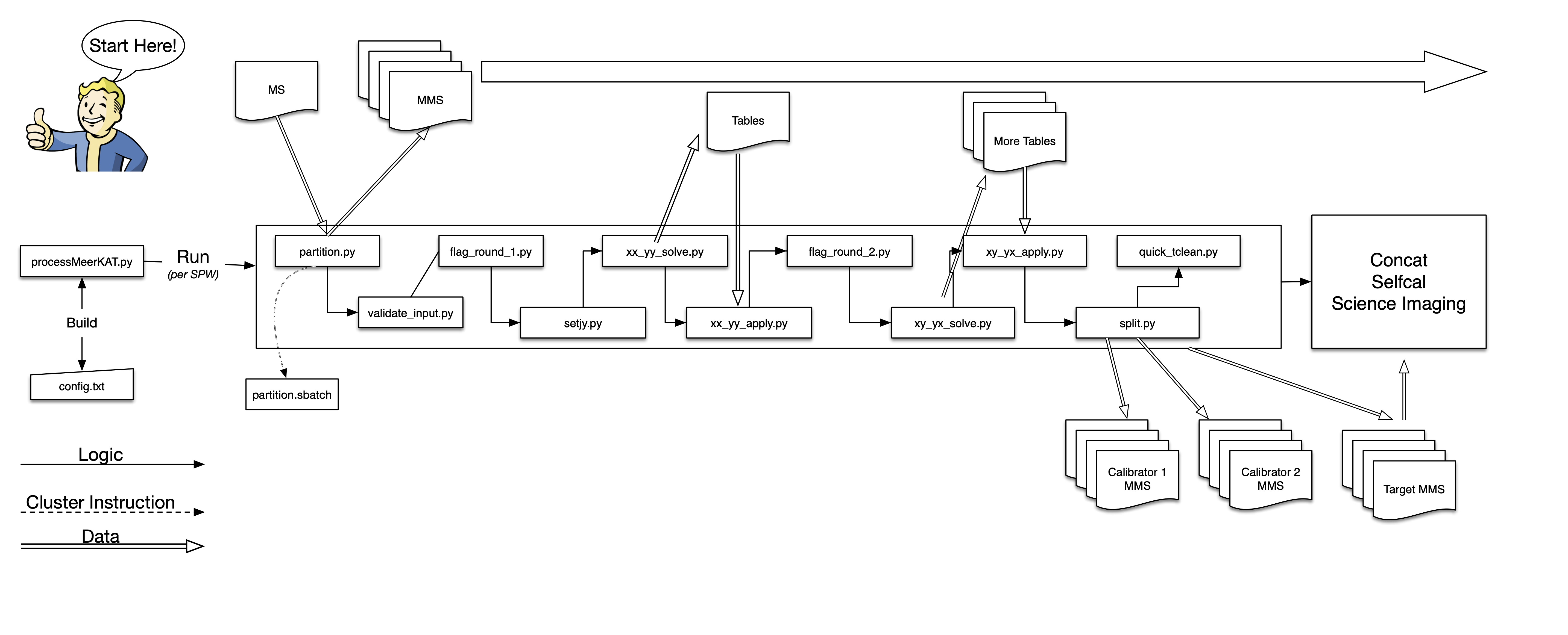
The pipeline is implemented as a series of SLURM sbatch scripts that in turn
call CASA scripts. The scripts are separated out to make optimal use of the
cluster, by splitting out sections that can be run in parallel (via casampi
and SLURM) and sections that must be run in serial.
New in Version 1.1 : The MeerKAT band can now be optionally separated out
into multiple spectral windows (SPWs) which are processed in parallel. Each SPW
is processed simultaneously (assuming there are a sufficient number of free
nodes on the cluster) bringing down the total runtime to . The
steps outlined below are run per-SPW. If this option is turned off, these steps
are run over the entire band.
The logical steps are:
Input validation : This script performs a few basic validity checks, on the default config file, and on the input MS. The existence of the input MS, and the data types of the inputs specified in the config file are all verified before the pipeline continues to the next steps. If reference antenna calculation is not requested, a simple check is performed to verify that the input reference antenna exists in the MS. Otherwise, the following paragraph describes the details of reference antenna calculation.
Reference antenna calculation : If the calcrefant parameter in the config
file is set to True, then this script is executed. It attempts to determine
the reference antenna by selecting the antenna with the smallest number of
flags.
Data partition : The input measurement set (MS) is partitioned into
a multi-measurement set
(MMS)
using the CASA task partition.
This task splits up the main MS into smaller SUBMSs that are individual units of a larger logical MMS. The number of SUBMSs created is equal to the number of scans in the input MS. Partitioning the data in this manner allows for more efficient use of computation while using MPI. If multiple SPWs are specified in the config file, each SPW is partitioned and calibrated independently and concurrently.
Flagging (round 1) : The first of two rounds of pre-calibration flagging. If
badfreqranges and badants are specified in the config file, the specified
frequency ranges and antennas are flagged prior to any further flagging
operations. These lists are also allowed to be empty. Following that the data
are clipped a nominal level of 50 Jy to eliminate the strongest RFI. The
tfcrop algorithm is run (with a conservative flagging threshold) independently
on the primary and secondary calibrators and the target(s).
setjy : The setjy task is run on the specified primary calibrators, which
writes the source model into the MS/MMS. Optionally if the --dopol option is
specified, this script detects if either 3C286 or 3C138 is present in the data
and includes the full Stokes model.
Parallel hand calibration : Standard delay, bandpass and gain calibration is run on the data. The time-dependent gain table contains solutions for both the primary and secondary calibrators. The fluxes are then bootstrapped from the primary to the secondary calibrator.
Flagging (round 2) : This time, both the tfcrop and rflag algorithms are
run independently on the primary and secondary calibrator and the target(s). The
rflag algorithm was not included in the first round of flagging because it is
sensitive to changes in the bandpass shape. After calibration, the bandpass is
much flatter allowing a median-filtering approach such as rflag to operate
much more effectively. The thresholds are lower than the first round as the data
is now calibrated, and therefore more well behaved. calibrated data.
Cross hand calibration : The cross-hand calibration (necessary for polarization observations) utilizes the unpolarized primary to solve for the leakages, and the polarization calibrator to solve for the XY phase. The pipeline uses the published full Stokes models as an input to solve for the XY phase. This approach requires only a single scan on the polarization calibrator. At the time of writing (April 2022) the standard polarization calibrators are all in the Northern hemisphere, and hence most MeerKAT observations are only able to have a single (or two) scans on the calibrator source, and our approach ensures sensible polarization results with such constraints.
Splitting out calibrated data : Finally each field in the MMS (whether calibrator or target) is split out and optionally averaged in time and frequency. If multiple SPWs are specified, this process is done per SPW. At this stage it is possible to either retain the data in an MMS or to convert it to an MS.
Concatenation (only multi-SPW) : If multiple SPWs are specified in the config, the split out MS/MMSs from each SPW are concatenated together. This final MS/MMS will internally have multiple SPWs.
Detailed description
What follows is a more detailed description of each of the steps described above, where applicable.
Partition* : During the partition stage, autocorrelations are excluded from
the data in order to reduce data volume. Further, if --dopol is not specified,
the cross-hand correlations (XY and YX) are also excluded from the data to
reduce overall data volume.
Flagging (round 1) : If a list of bad frequency ranges and bad antennas is
specified, those are flagged. Subsequently, flagdata is called on the
calibrators and target sources with conservative limits to clip out the worst
RFI. It also makes a single call to tfcrop to flag data at a limit.
tfcrop in this case is preferred, since the as yet uncalibrated bandpass shape
should be taken care of by fitting a piecewise polynomial across the band.
setjy : By default, the ‘Stevens-Reynolds 2016’ flux scale is used. If the
primary calibrator J0408-6545 is present and is specified as the flux
calibrator, a broadband Stokes I model is used via the manual mode of setjy.
This model is courtesy SARAO.
Cross hand calibration : The full Stokes calibration procedure is done identically across each SPW specified in the config file.
The cross-hand calibration performs the following steps:
- Bandpass calibration on the primary calibrator
- Leakage calibration on the unpolarized primary calibrator (typically one of either J1939-6342 or J0408-6545)
- Gain calibration (using gaintype=’T’ in CASA) on the primary, secondary and polarization calibrators
- XY Phase calibration on the polarization calibrator
We opt to use gaintype=’T’ in the CASA gaincal task since it preserves the
relative gains of the X & Y feeds. This is important because in the case of the
secondary and polarization calibrators, the Stokes Q power of the source is
retained in the difference of the XX and YY correlations, and correcting for
each correlation independently without accounting for the source polarization
will reduce the Stokes Q signal to 0 since any relative change between the two
will be assumed to be due to instrumental effects.
While in principle during the setjy step we set the full Stokes model of the
polarization calibrator, we find that the CASA gaincal task does not reliably
pick this model up while calibrating with gaintype='G'. However the
gaintype='XYf+QU' mode does recognize the input model and yields sensible XY
phase solutions. Please note that after XY phase solutions the resulting
calibration solutions could still contain an arbitrary polarization angle
offset corresponding to a feed offset. This offset can be measured by
generating cubes of the polarization calibrator, and any measured offsets can
be corrected for in the image domain or by modifying the calibration tables
directly. At this time the pipeline does not support either of these
operations, and it will have to be done by the user after the pipeline has
completed.